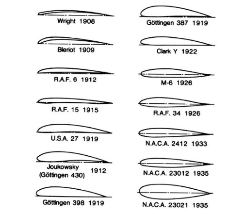
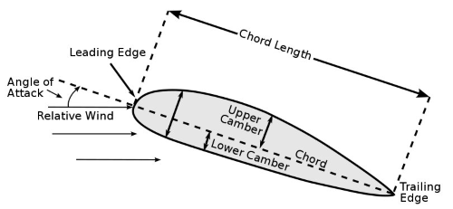
Some of the first research on curvatures or the camber of a wing, known as an airfoil, was conducted by the famous Wright brothers.
As powered flight was in its infancy, airfoils were traditionally hand-built for each aircraft.
Prior to World War 1, there was no standardized airfoil that was used on multiple planes, and not many people were doing research to create one.
Some earlier work was done by the British government at the National Physical Laboratory (NPL), and it resulted in a series of Royal Aircraft Factory airfoils.
One type of airfoil, called the RAF 6, was used on World War 1 aircraft.
Related Article – Instrument Proficiency Check (IPC): 4 Things You Need To Know
In the United States, many of the American planes used RAF sections, and others relied on a shape designed by Frenchman Alexandre Gustave Eiffel, the designer of the Eiffel Tower.
The National Advisory Committee on Aeronautics (NACA) was created in 1915, and one of the main goals of the members was to create better airfoils.
According to the first NACA Annual Report, there was a need for “the evolution of more efficient wing sections of practical form, embodying suitable dimensions for an economical structure, with moderate travel of the centre of pressure and still affording a large angle of attack combined with efficient action.”
In 1917, the NACA Technical Report No. 18 titled “Aerofoils and Aerofoil Structural Combinations,” was released.
According to the authors, mathematical theory still hadn’t been applied to airfoil design.
At that point, the work was mostly trial and error.
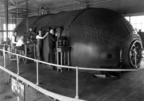
Multiple brass airfoil models, with a span of 18 inches and a chord of 3 inches in a wide tunnel, were tested.
Related Article – Airline Transport Pilot Certificate (ATP): 4 Things You Need To Know
After the release of the report, the U.S.A. series of airfoils emerged, and there was reported wind tunnel data for the U.S.A. 1 through 6 sections.
While there were only small variations in the airfoil designs, they caused significant differences in aerodynamic performance.
Because of this, they proceeded cautiously with research.
One of the most important reports, Technical Report No. 460, “The Characteristics of 78 Related Airfoil Sections from Tests in the Variable-Density Wind Tunnel,” was issued by NACA in 1933.
It was in this report where the NACA four-digit airfoil series was detailed by the authors.
The four digits were responsible for the overall shape of the airfoil.
The NACA airfoil 2412 had a max camber of 2 percent of the length of the cord, and this was shown in the first digit.
The second digit indicated the maximum camber that occurred at a distance of 0.4 chord from the leading edge, and the last two digits represented the maximum thickness of the airfoil at 12 percent of the overall width of the wing.
Airplane designers did not use all 78 of the airfoil sections, but the aircraft manufacturers had a large selection because of the testing data.
The report led to the widespread use of the NACA airfoils, and the NACA 2412 was still used on some planes over a half a century later.
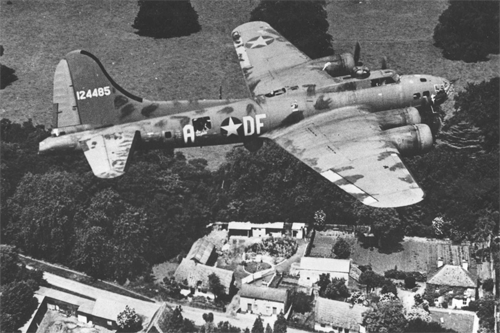
Another important report for the development of the airfoil was NACA Technical Report 460.
The contents of that report were responsible for the design of many U.S. aircraft, including some used during World War II.
Some of those aircraft that relied on it were the DC-3 transport, the B-17 Flying Fortress bomber, and the twin-tailed P-38 Lightning interceptor.
It was in the late 1930s when the NACA looked for ways to increase the maximum lift of the airfoil.
They released the NACA five-digit airfoil series along with airfoils like the 23012, used on aircraft such as the Beechcraft Bonanza.
The camber and thickness was represented in the first and last two digits, and the second digit indicated twentieths of a chord rather than tenths.
The middle digit represented either a straight mean camber line or a curved mean camber line.
Related Article – 12 Runway Markings and Signs Explained By An Actual Pilot
The “meanline” is the line that is equidistant at all points between the upper and lower surfaces of the airfoil.
One of the issues with the NACA airfoil research was that an entire wing section could not be tested.
The wind tunnel that they had at the time was not large enough to mount a wing, so they had to complete the testing in parts.
Because of this limitation, the researchers were not able to determine the effects of the airflow at the tip of the wing.
This piece of information was important to understand the overall performance of the wing.
NACA remedied this problem in 1939 when they built a low-turbulence two-dimensional wind tunnel at Langley Research Center in Virginia.
It was created specifically for testing airfoils, and NACA aerodynamics used it to conduct a large number of tests on different airfoil designs.
Towards the end of the 1930s, NACA aerodynamics had a strong interest in laminar-flow airfoils, which had their maximum thickness far back from the leading edge.
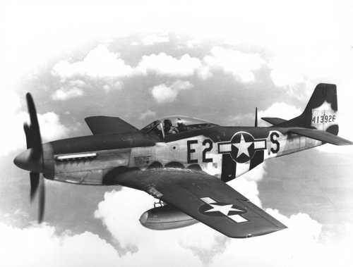
The North American P-51 Mustang was the first aircraft to utilize these new airfoils that had low-drag qualities, and many high-speed aircraft still use them today.
Related Article – 14 Taxiway Markings, Signs, and Lights Explained By An Actual Pilot
The airfoils work great at high speeds when used outside of the wind tunnel.
When NACA shifted their focus to supersonic and hypersonic aerodynamics in 1950, airfoil development was all but stopped.
It re-emerged once again in 1965 with the huge development of the NASA supercritical airfoil by Richard T. Whitcomb.
The design of the wings with high critical Mach numbers allowed it to operate at high speeds.
U.S. airfoil research started up again after this development, and it was led by the National Aeronautics and Space Administration (NASA), which was created in 1958 and absorbed the NACA.
Low-speed airfoil series were developed for general aviation on light airplanes, and they had better lifting characteristics.
There was less drag due to the smaller wing areas, which was important for small private aircraft.
Even in our current times, some aircraft still use the 1930s and 1940s designed NACA four-digit and five-digit airfoil sections.
Related Article – 5 Best Low Time Pilot Jobs With 250 Hours
